


Connecting a Router to a WAN via Serial Interface: Back-to-Back Cables
Lab Objective
- Identify serial interfaces on a router
- Find the correct connection point for serial cables on the router
- Use a serial cable to connect to a router
- Identify back-to-back serial cables for connecting two routers directly through serial interfaces
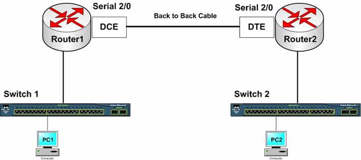
This lab connects two routers directly through their serial interfaces to simulate a WAN link. These routers could be in any geographic location — a different city or even a different country — connected through WAN links.
🛠️ Equipment Needed for This Lab
- 2 Cisco routers with serial interfaces
- 2 PCs
- Back-to-back serial cable
Step 1: Identify Serial Interfaces on the Router
Look at the back of the router. What interfaces do you see?
What’s your router model? _____________
How many interfaces does your router have? _____________
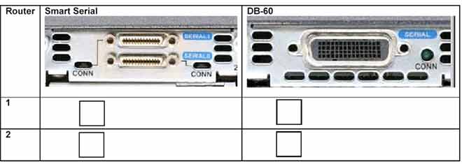
Depending on your router model, it may not have a serial interface. If you need one, you can add a serial module to the router. Your router may have one or more serial interfaces. Serial interfaces connect to WAN networks — study the image below carefully.
The image below shows DB-60 and Smart Serial interfaces.
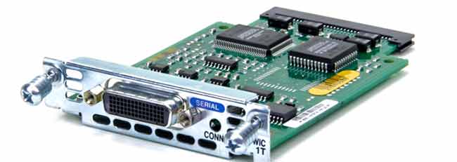
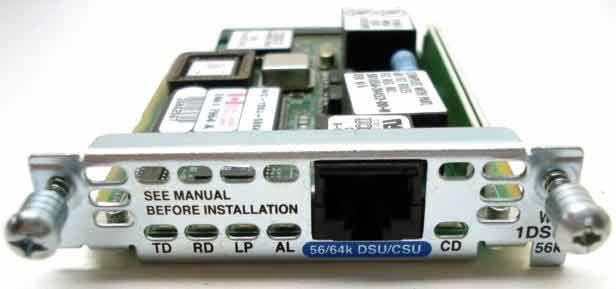
If your router doesn’t have a serial port — or you need an extra one — you can add a serial module. The image below shows a serial module.
Serial interfaces connect to WAN networks and telecommunications lines — leased lines, satellite modems, and various WAN services.
CSU/DSU and Clocking
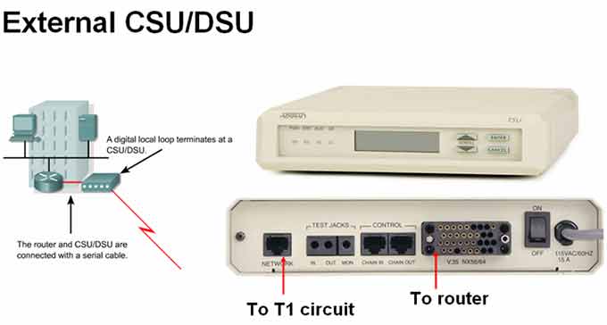
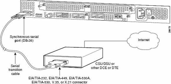
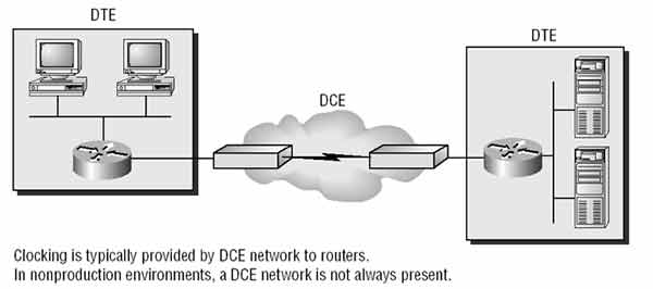
A CSU/DSU is a hardware device that serves as the endpoint for a WAN link from the telecommunications provider. It provides clocking — timing and speed — for the router’s serial interface. The CSU/DSU sits at the boundary between the internal LAN and the WAN connection.
Back-to-Back Cables and Lab Simulation
In lab environments — like Cisco training classes — two routers connect directly through their serial interfaces using back-to-back serial cables. There’s no CSU/DSU in this setup, so the connection simulates a WAN link.
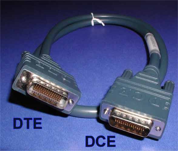
Back-to-back cables have a DCE connector on one end and a DTE connector on the other. They connect two routers directly without a CSU/DSU.
Key rule: Whichever router interface connects to the DCE end of the back-to-back cable must provide clocking. Configure this with the clock rate command on that interface.
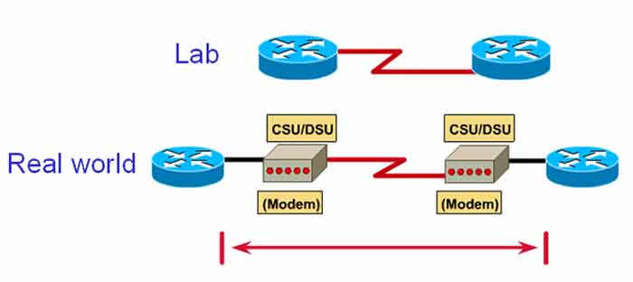
In this lab, we’re not connecting to a real WAN service. We’re simulating one in a lab environment. We connect two routers directly with a back-to-back serial cable — no CSU/DSU. The router interface connected to the DCE cable must provide clocking for the opposite interface connected to the DTE cable.
Use a back-to-back serial cable to connect two routers directly through their serial interfaces. One end is DCE, the other is DTE — as shown in the image below.
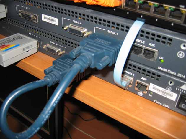
The image below shows two Cisco routers connected through their serial interfaces using a back-to-back serial cable.
DCE vs. DTE at a Glance
| Feature | DCE (Data Circuit-Terminating Equipment) | DTE (Data Terminal Equipment) |
|---|---|---|
| Clocking | Provides clocking | Receives clocking |
| Command Needed | clock rate |
None |
| Typical Role | CSU/DSU side, service provider edge | Router, terminal, customer premises |
| In Back-to-Back Cable | One end | Other end |
Where Serial Interfaces Are Used
| WAN Service | Description |
|---|---|
| Leased Line | Dedicated point-to-point connection from the telecom provider |
| Satellite Modem | Satellite-based internet or WAN connectivity |
| Other WAN Services | Frame Relay, MPLS, and similar WAN technologies |
✅ Key Takeaways
- Serial interfaces connect routers to WAN networks.
- DB-60 and Smart Serial are the two main serial connector types on Cisco routers.
- CSU/DSU provides clocking for the serial interface in real WAN links.
- Back-to-back cables connect two routers directly for lab simulation — no CSU/DSU needed.
- One end of a back-to-back cable is DCE, the other is DTE.
- The interface connected to DCE must provide clocking with the
clock ratecommand. - Serial modules (WIC cards) add serial ports to routers that don’t have them.
